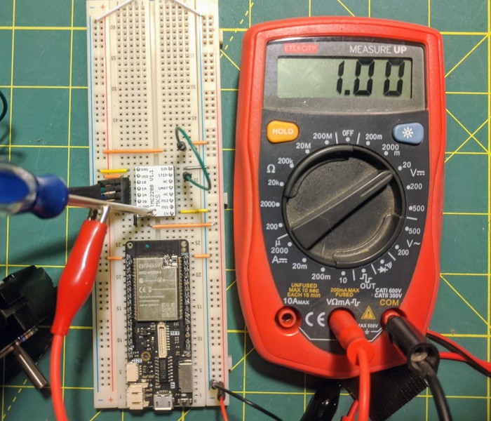
Stepper drivers are used as a simpler interface to control stepper motors, here we use the esp-idf RMT peripheral to send step pulses
Context
The naive implementation of driving the 4 stepper channels through a l298n datasheet motor driver works but has several significant drawbacks.
- Requires 4 RMT channels
- Will overheat without current limiting
- Microstepping requires PWM on the RMT, is a PITA
Solution Postulation
Content exploration led me to the Marco Reps YouTube channel who has an interesting video on motion control
The Trinamic TMC2208 (datasheet) stepper driver provides a more ergonomic step+direction interface, where a direction pin can be low/high to define which direction, and the step pin is pulsed to increment the stepper over.
Because 3d printers tend to use stepper motors there is a standard Dual Inline Pin form factor that is widely and cheaply available. This specific breakout is the Gowoops 3D Printer Stepper Motor Driver
Wiring
The 16 pins on this breakout and what they connect to are below:
| Pin | Description | Pin | Description |
|---|---|---|---|
| GND | Ground | DIR | Direction Selector |
| VDD/VIO | Logic Supply Voltage | STEP | Step Trigger |
| M2B | Coil 2 + | NC | Not Connected |
| M2A | Coil 2 - | UART | Serial Configuration |
| M1A | Coil 1 - | NC | Not Connected |
| M1B | Coil 1 + | MS2 | Microstep Selector 2 |
| GND | Ground | MS1 | Microstep Selector 1 |
| VM | Motor Supply Voltage | EN | Enable stepper |
Wiring sequence for an esp32:
- GND -> Common Ground
- ESP32 GND -> Common Ground
- ESP32 3V -> VDD
- Stepper Black -> M1B
- Stepper Green -> M1A
- Stepper Blue -> M2A
- Stepper Red -> M2B
- Motor Power Ground -> Common Ground
- Motor Power + -> VM
- EN -> Low (Ground)
- Dir -> Low
- Step -> Low
Tuning current
This driver limit the current set to the motor, tuned using a resistor. The specific packaging here has a trim pot on top that exposes a reference voltage (potentiometer body to ground is Vref)

Vref = voltage on stepper pot, 0 .. 2.5V Lrms = RMS current per phase Lrms = Lmax / 1.41
Our steppers are Nema 17, specifically 17HS4401. They accept a max current of 1.7A
Lrms = 0.71
(insert picture)
Vref = 0 .. 2.5V
Process Irms = 325mV
- Lrms = (Vref _ 1.77A) / 2.5V = Vref _ 0.71
- Vref = Lrms / 0.71
- Vref = 0.71 / 0.71
- Vref = 1

Testing Notes
We are pulling 3.3v from logic and connecting it to STEP to see if anything happens
Nothing

Attaching EN to ground enables motor
Motor starts spinning eratically
Shorting step to ground stops motor
Shorting step to high stops motor

Guess:
Hates floating
Writing code
Using esp32 my friend Benjamin wrote a codings that drives GPIO 18 high and low.
Our code drives the pin high and low 20 times per second. After powering up the stepper starts spinning very very slowly, approximately 1 rotation every 60 seconds.
Datasheet page 8:

With MS1 and MS2 both low the stepper defaults to 1/8 microstepping, and the stepper is 200 full steps per revolution meaning
20 microsteps per second is 2.5 steps per second
200 steps per revolution / 2.5 seconds per step is 80 seconds per revolution?
Ah well, probably a software issue.