Building a clean stepper loop
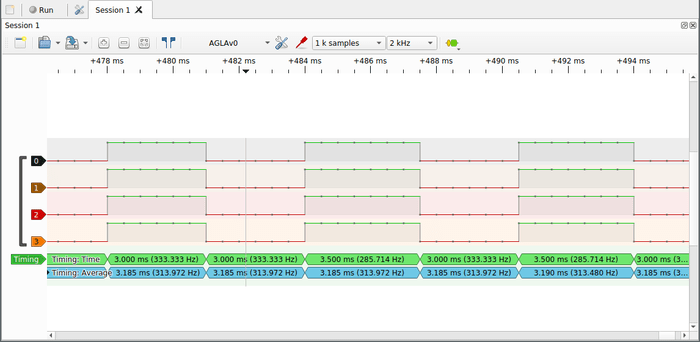
The steps were set up to write two values at once with a repeating pattern 00 11 00 11 pattern of on/off on the first channel, with 2x 500 ticks per pulse. With a clock of 80mhz and a clock divider of 255 we would expect each pulse to last 1/80,000,000*255*1000s, or 3.1875ms
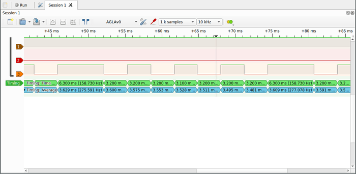
The timing is a bit off, and there is an odd doubled up phase. Does this have to do with a delay in looping or is there an off by one somewhere? By increasing the delay we can check if the long pulse also increases...

There's an open issue over in the micropython repo investigating this, pointing towards the esp repo
This comment solved the issue, pointing to an interference between a software interrupt based on loop_en and a hardware interrupt with rmt_set_tx_loop_mode. The fix was on master 11 days before
    for (int i=0; i < NUM_PINS; i++) {
        ESP_ERROR_CHECK(rmt_fill_tx_items(RMT_CHANNEL_0 + i, _rmt_buffer[i], RMT_BUFFER_SIZE + 1, false));
        rmt_set_tx_intr_en(RMT_CHANNEL_0 + i, false);
    }

    for (int i=0; i < NUM_PINS; i++) {
        rmt_set_tx_loop_mode(RMT_CHANNEL_0 + i, true);
    }
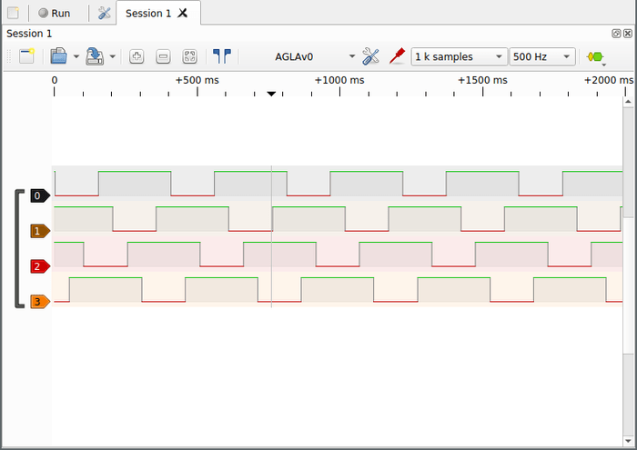
This fix provided an absolutely beautiful square wave:

Switching over to the stepper sequence nets us an absolutely beautiful and perfectly looped thrum of steps:

Stepper API
The source for a stepper sequence will be a function that when called returns a pair of step count and delay.
Key elements are rmt_set_tx_thr_intr_en which allows an interrupt to fire when a certain number of items have been sent. An example of this can be found here
At a high level I would like to
- call this function and store the steps remaining for this operation
- translating it to an intermediate buffer of step information
- copying that buffer into the RMT peripherals memory
By alternatively copying into the first half and second half of the RMT memory while it is reading from the other half we can have it transmit continuously without interruption.
At a lower level the plan is to:
- Per stepper store:
-
- RMT step buffer (half of size)
-
- Absolute step count
-
- Steps remaining
-
- Direction of step
-
- Current portion of buffer
- Write a function that:
-
- Consumes the source function
-
- Calculates the steps remaining and ticks per step
-
- Updating the stepper state
-
- Writes rmt items to memory
RMT cannot use custom interrupts
Throughout the course of writing it was soon obvious that the framebuffer approach was incompatible with esp idf v4. The documentation notes
When calling rmt_driver_install() to use the system RMT driver, a default ISR is being installed. In such a case you cannot register a generic ISR handler with rmt_isr_register().
Roger, and note rmt_driver_install is the only method to allocate p_rmt_obj which must exist for using any of the documented rmt code.
This issue was discovered by the author of FastLED and includes a stacktrace I'll reproduce here for ease of searching for this issue:
I (1035) fastled: init
Guru Meditation Error: Core 0 panic'ed (LoadProhibited). Exception was un handled.
Core 0 register dump:
PC : 0x400fd1ab PS : 0x00060c33 A0 : 0x800f917e A1 : 0x3ffbbea0
0x400fd1ab: rmt_set_tx_thr_intr_en at /home/micha/esp-open-sdk/esp32/esp-idf/components/driver/rmt.c:389 (discriminator 2)
0x400fd1a8: rmt_set_tx_thr_intr_en at /home/micha/esp-open-sdk/esp32/esp-idf/components/driver/rmt.c:389 (discriminator 2)
0x400f917b: ClocklessController<18, 60, 150, 90, (EOrder)66, 0, false, 5>: :showPixels(PixelController<(EOrder)66, 1, 4294967295u>&) at /home/micha/projects/projects_esp32/httpd/components/FastLED-idf/include/clockless_rmt_ esp32.h:264
(inlined by) ClocklessController<18, 60, 150, 90, (EOrder)66, 0, false, 5 >::showPixels(PixelController<(EOrder)66, 1, 4294967295u>&) at /home/micha/projects/projects_esp32/httpd/components/FastLED-idf/include/clockless_rm t_esp32.h:294
Luckily for us the same refactor that forced the use of p_rmt_object also created the rmt_ll.h low level abstraction.
Rewriting the code eliminating any imports of rmt.h and using rmt_ll, as well as using direct memory access both allowed the use of an interrupt and eliminated allocating redundant buffers.
Here is how the driver was initialized using code copied from rmt.c:
    periph_module_enable(PERIPH_RMT_MODULE);
    rmt_hal_init(&stepper->_hal);

    for (size_t i = 0; i < NUM_PINS; i++)
    {
        rmt_channel_t channel = channels_a[i];
        gpio_num_t gpio_num = pins_a[i];
        stepper->_rmt_channel[i] = channel;
        //rmt_config_t config = RMT_DEFAULT_CONFIG_TX(pins_a[i], channel);
        //config.tx_config.loop_en = false;
        //config.clk_div = RMT_DIV;

        PIN_FUNC_SELECT(GPIO_PIN_MUX_REG[gpio_num], PIN_FUNC_GPIO);
        gpio_set_direction(gpio_num, GPIO_MODE_OUTPUT);
        gpio_matrix_out(gpio_num, RMT_SIG_OUT0_IDX + channel, 0, 0);

        rmt_ll_set_counter_clock_div(&RMT, channel, RMT_DIV);
        rmt_ll_enable_mem_access(&RMT, true);
        rmt_ll_set_counter_clock_src(&RMT, channel, RMT_BASECLK_APB);
        rmt_ll_set_mem_blocks(&RMT, channel, 1);
        rmt_ll_set_mem_owner(&RMT, channel, RMT_MEM_OWNER_HW);

        rmt_ll_enable_tx_cyclic(&RMT, channel, false);
        rmt_ll_enable_tx_pingpong(&RMT, true);
        /*Set idle level */
        rmt_ll_enable_tx_idle(&RMT, channel, false);
        rmt_ll_set_tx_idle_level(&RMT, channel, 0);
        /*Set carrier*/
        rmt_ll_enable_tx_carrier(&RMT, channel, false);
        rmt_ll_set_carrier_to_level(&RMT, channel, 0);
        rmt_ll_set_carrier_high_low_ticks(&RMT, channel, 0, 0);

        rmt_hal_channel_reset(&stepper->_hal, channel);

        stepper->_tx_buf[i] = (volatile rmt_item32_t *)&RMTMEM.chan[channel].data32;
        for (int b = 0; b < (RMT_BUFFER_SIZE * RMT_BUFFER_COUNT + 1); b++)
        {
            stepper->_tx_buf[i][b].val = end_marker.val;
        }
    }
    rmt_ll_set_tx_limit(stepper->_hal.regs, channels_a[0], RMT_BUFFER_SIZE);
    rmt_ll_enable_tx_thres_interrupt(stepper->_hal.regs, channels_a[0], true);
Debugging interrupts
This stack trace appeared as soon as I tried to print inside of an interrupt
0x4008dca5: invoke_abort at /nix/store/xffg6lg696k4j5cpnmakyvj3vvpjsabv-esp-idf/components/esp32/panic.c:157
0x4008e039: abort at /nix/store/xffg6lg696k4j5cpnmakyvj3vvpjsabv-esp-idf/components/esp32/panic.c:174
0x40082aea: lock_acquire_generic at /nix/store/xffg6lg696k4j5cpnmakyvj3vvpjsabv-esp-idf/components/newlib/locks.c:143
0x40082c0d: _lock_acquire_recursive at /nix/store/xffg6lg696k4j5cpnmakyvj3vvpjsabv-esp-idf/components/newlib/locks.c:171
0x40139382: _vfprintf_r at /builds/idf/crosstool-NG/.build/xtensa-esp32-elf/src/newlib/newlib/libc/stdio/vfprintf.c:853 (discriminator 2)
0x4012fc19: printf at /builds/idf/crosstool-NG/.build/xtensa-esp32-elf/src/newlib/newlib/libc/stdio/printf.c:56
0x40082d36: stepper_isr at /home/username/projects/hanging-plotter/esp32/polargraph/build/../main/stepper.c:219
Checking out the source for locks.c:143 the note
/_ recursive mutexes make no sense in ISR context _/
Made things pretty clear. Using the search term esp idf print in isr I found a forum thread that pointed towards the poorly documented ets_printf which works in interrupts.
Finalization
After fixing some minor bugs involving an integer overflow (-128 to 127!) and stepping direction (reverse is -1 not 0!) the driver worked! For a single stepper. As it turns out driving multiple steppers in sync requires an almost complete redesign.
Expansion, or product driven API design
Designing an api still feels like an abstract art, that there isn't a methodology for driving utility up and complexity down.
In this specific case the api is fairly simple,
// Function returning an array of two int16_ts representing [steps, us per step]
typedef int32_t *(*stepper_get_steps_t)();

void stepper_init(gpio_num_t[4], rmt_channel_t[4], stepper_get_steps_t);
void stepper_start();
Setup the stepper with pins and channels, start it, and provide it with a way to retrieve [number of steps, microseconds per step]. Currently bluetooth sets a static variable which is fed into the stepper_get_steps_t function.
One of the design goals of this project is to synchronize multiple steppers,. The shortest step from this design is to provide two get_steps functions and ensure that steps * microseconds always ends up the same. This might work but relies on the programmer constructing correct data, and as a programmer I know that is impractical.
Make it hard to do the wrong thing
We could provide the stepper system with a data structure similar to:
typedef struct
{
    int16_t steps_a;
    int16_t us_per_step_a;
    int16_t steps_b;
    int16_t us_per_step_b;
} stepper_plan_t;
and use assertions to verify that steps_a * us_per_step_a = steps_b * us_per_step_b. When two aspects of a data structure do not align it loses internal consistency. This data structure has 4 degrees of freedom, 4 ways values can change.
Reduce the degrees of freedom to the minimum to keep data structures internally consistent
By tweaking the structure to:
typedef struct
{
    int32_t steps[NUM_STEPPERS];
    uint16_t duration;
} stepper_task_t;
The data structure is forced to internal consistency. Negative time does not make sense, and it is guaranteed that both steppers will complete in the same duration.
Task Buffer
Because there exists a buffer of steps in the RMT module it is possible that one stepper will consume tasks faster than the other, meaning we need to individually track which task each stepper is on, and whether a stepper has completed the task.
The task buffer struct looks like this:
#define STEPPER_TASK_BUF RMT_BUFFER_SIZE*RMT_BUFFER_COUNT

static stepper_task_t stepper_tasks[STEPPER_TASK_BUF];
static uint8_t stepper_task_active[STEPPER_TASK_BUF];
The size is calculated such that in the degenerate case of one stepper having many steps per task and the other having one step per task it is possible to fill the RMT buffer with one task per RMT item.
Active is needed such that the task can immutable and state can most easily be reasoned about.
Getting this code to work was quite tricky, a critical debugging step was outputting the stepper state in a manner that enabled a quick visual understanding of the state of the system over time:
Stepper 1: Getting new task
PHASE: 5
[1]   1120  30v ( 1061) > 7654321076543210 < [ 7654321076543210 ] {         %*       }
[0]   -144  26v ( 1061) [ 7654321076543210 ] > 7654321076543210 < {          *       }
[1]   1104  14v ( 1061) [ 7654321076543210 ] > 7654321076543210 < {          *       }
[0]   -160  10v ( 1061) > 7654321076543210 < [ 7654321076543210 ] {          *       }
Stepper 1: Getting new task
PHASE: 5
[1]   1088  28v ( 1061) > 7654321076543210 < [ 7654321076543210 ] {          %*      }
[0]   -176  24v ( 1061) [ 7654321076543210 ] > 7654321076543210 < {           *      }
[1]   1072  12v ( 1061) [ 7654321076543210 ] > 7654321076543210 < {           *      }
[0]   -192   8v ( 1061) > 7654321076543210 < [ 7654321076543210 ] {           *      }
[stepper id] abs-steps steps-remaining(direction) (ticks per step) > active rmt buffer < [ steps in rmt buffer ] { task buffer state }Task Buffer Algorithm
Steppers share:
- A ring buffer of tasks, initially empty
Each stepper has:
- Absolute step count
- Steps remaining
- Step direction
- How many ticks per step
- The current task index
- Which tasks are active
- Which segment of the RMT buffer is active
- Several RMT buffers of pin hi/low + duration
- An interrupt that fires when a RMT segment is complete
To setup run the following algorithm repeatedly on each stepper until the RMT buffer is full. Start the RMT module on all channels, looping when it reaches the end
When the interrupt fires:
- Look up the stepper signal configuration based on current absolute step count
- Write value to RMT buffer, decrement steps remaining
- If steps remaining is 0 get another task:
- Mark the current task inactive
- Set the steppers current task to the next one in the buffer
- If no other stepper has marked the current task active:
- Call the task callback to fetch the next task
- Write the task to the buffer
- Otherwise use the task already in the buffer
- Mark the task active for this stepper
- Copy (absolute value of) steps remaining from the task
- Set step direction based on sign of steps remaining
- Calculate ticks per step based on task step count and duration
- Repeat until the buffer is full
- Switch the rmt segment to the next one
This algorithm is missing:
- What to do if a stepper has no steps in a task (set direction to 0, step count to 100)
- What to do if the step duration is longer than possible with the RMT module (break it into multiple rmt items)
- What to do if the step duration is shorter than possible (slow down the other stepper?)
- Stopping the stepper
Next steps
The simple stepper drivers being used do not limit current and rapidly overheat when attached to a battery, and the pulley geometry does not support the weight of everything.
Only one stepper will operate at once, if one is unplugged the other works fine.
By switching to "pancake" steppers and a current limited step/direction driver it should be possible to use the current physical structure to pilot it around with bluetooth.
C has been a miserable development experience of not understanding what's going on and not trusting it when it pretends to work. Let's use a more modern language (rust) and see how to write tests for embedded code
